PCB Assembly Guide for Data Gators
Read on for instructions for how to assemble an Data Gator board and example pictures of the finished product.
Prerequisites
-
Should have DG PCBs. Instructions for getting boards in [[PCB_Fabrication_Guide PCB Fabrication Guide]]. - All surface mount components should be installed.
- All through-hole components from the [[Bill of Materials]].
-
Have all tools or alternatives listed in the [[PCB_Assembly_Guide#Equipment equipment list]].
Equipment
[!note] The following equipment is recommended for this project, but no specific brands/varieties are required. Example products are linked for quick reference.
| Item | Description | Example Link |
|---|---|---|
| Soldering Iron | Need a soldering iron with a moderately small tip. | soldering iron search on adafruit |
| Solder | Any solder wire will do, but thickness around 0.8mm or less is recommended. | solder wire options |
| Solder Wick (optional) | Solder wick is a fallback option when things go wrong. Even if you don’t need it now, you likely will later. | solder wick |
| Solder Pump (optional) | Like solder wick, this is essential for fixing mistakes and clearing solder out of through holes and vias. | solder pump - kotto, solder pump - engineer |
| Tweezers | Good for holding small components while soldering to save your fingers. | ifixit tweezers set |
| Flush Cutters | Good for rework and clean up. | hakko flush cutters |
| Third Hand and/or Vice (optional) | Something to hold your work is not mandatory - necessity is the mother of invention after all - but this may save you significant head ache. | helping hands - kotto |
Instructions
Initial PCB + SMD Components
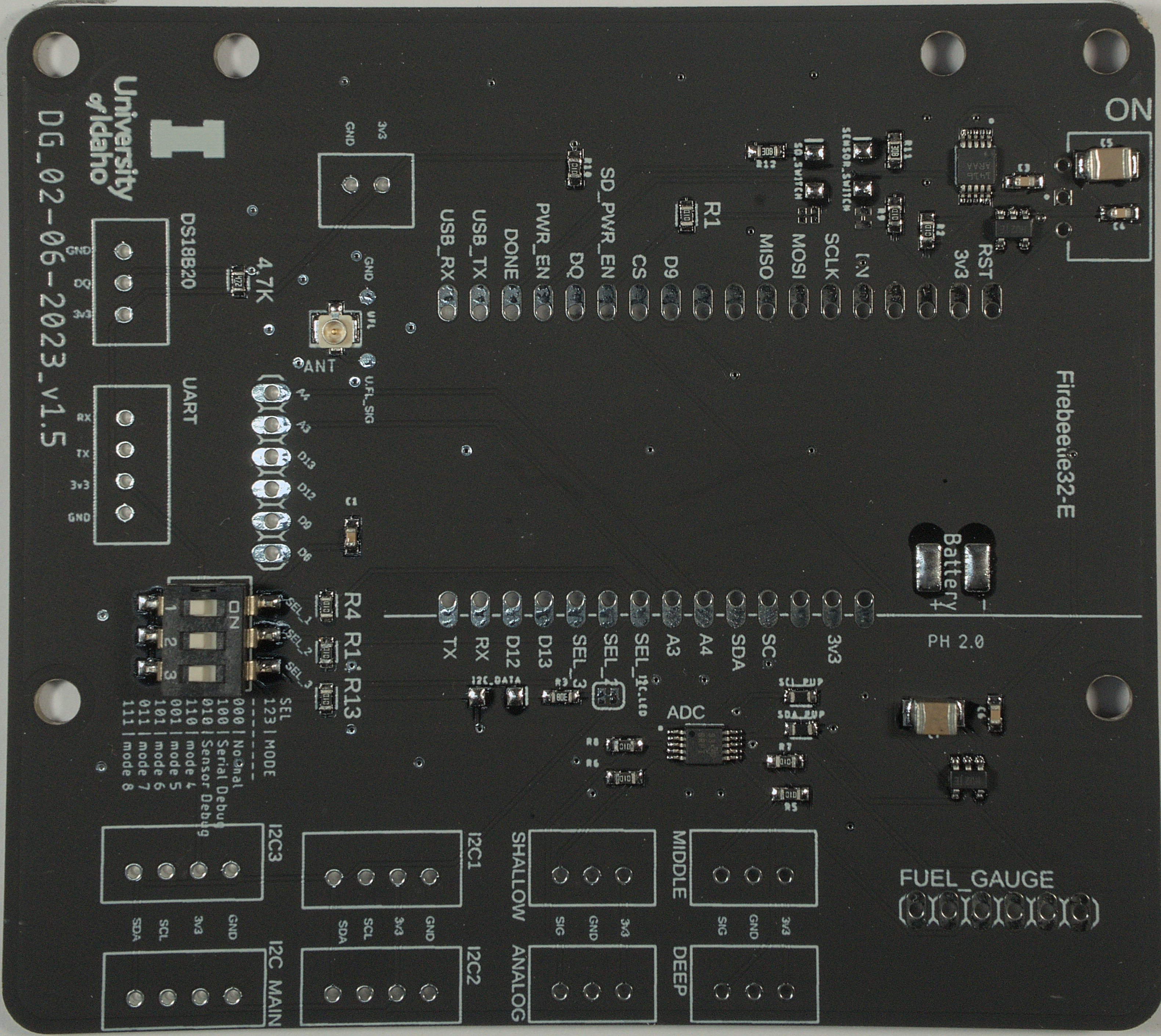
-
Solder Firebeetle ESP32 micro-controller (uC) to PCB.
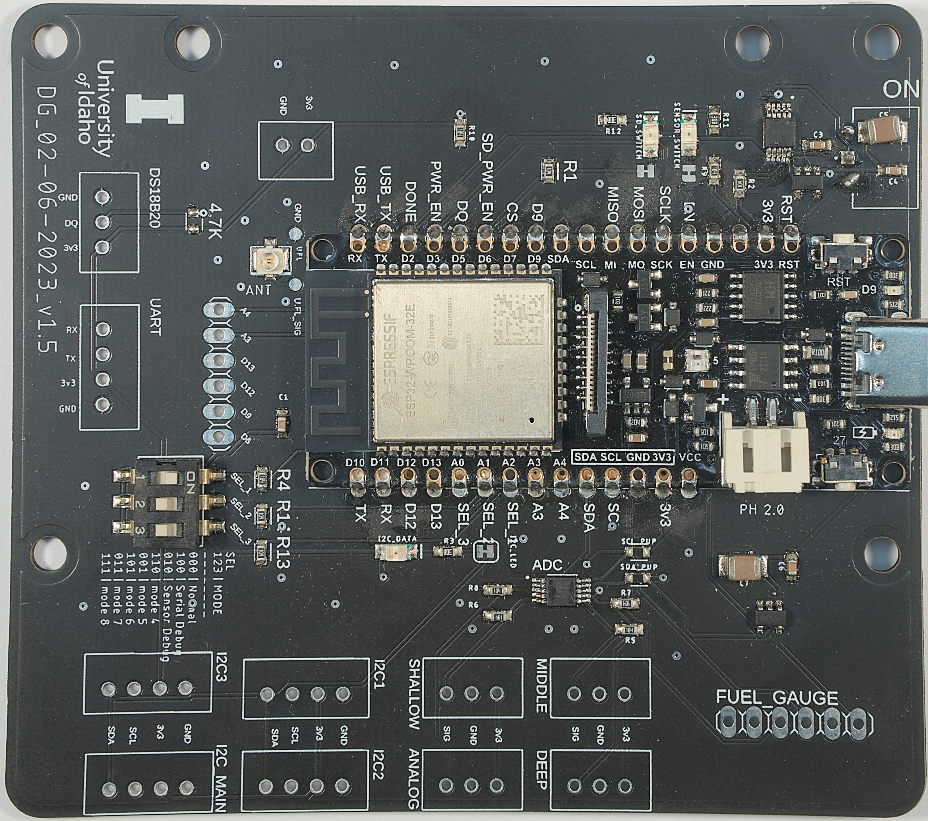
[!note] Tips for Alignment It can be difficult to align the micro-controller board with the PCB pads for soldering and keep them aligned. To avoid misalignment, use the pin headers included with the micro-controller to align holes by placing the micro-controller on the PCB, aligning with holes, then placing the pin header through the holes. You can then solder the first and last hole of a side to keep the board in place, remove the pin header, and finish soldering both sides.
-
Solder switch to PCB.
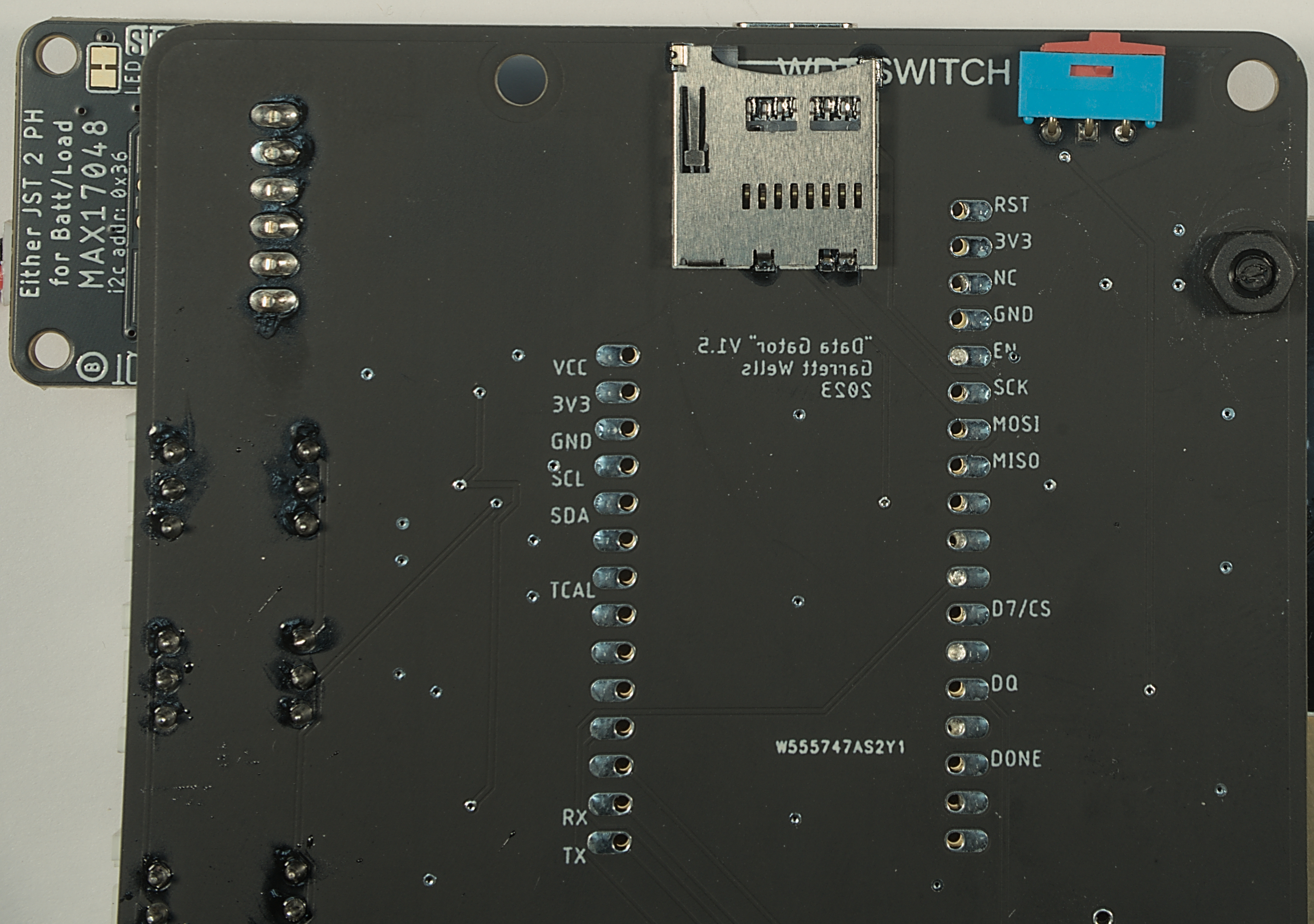
-
Solder Fuel Guage to PCB.
-
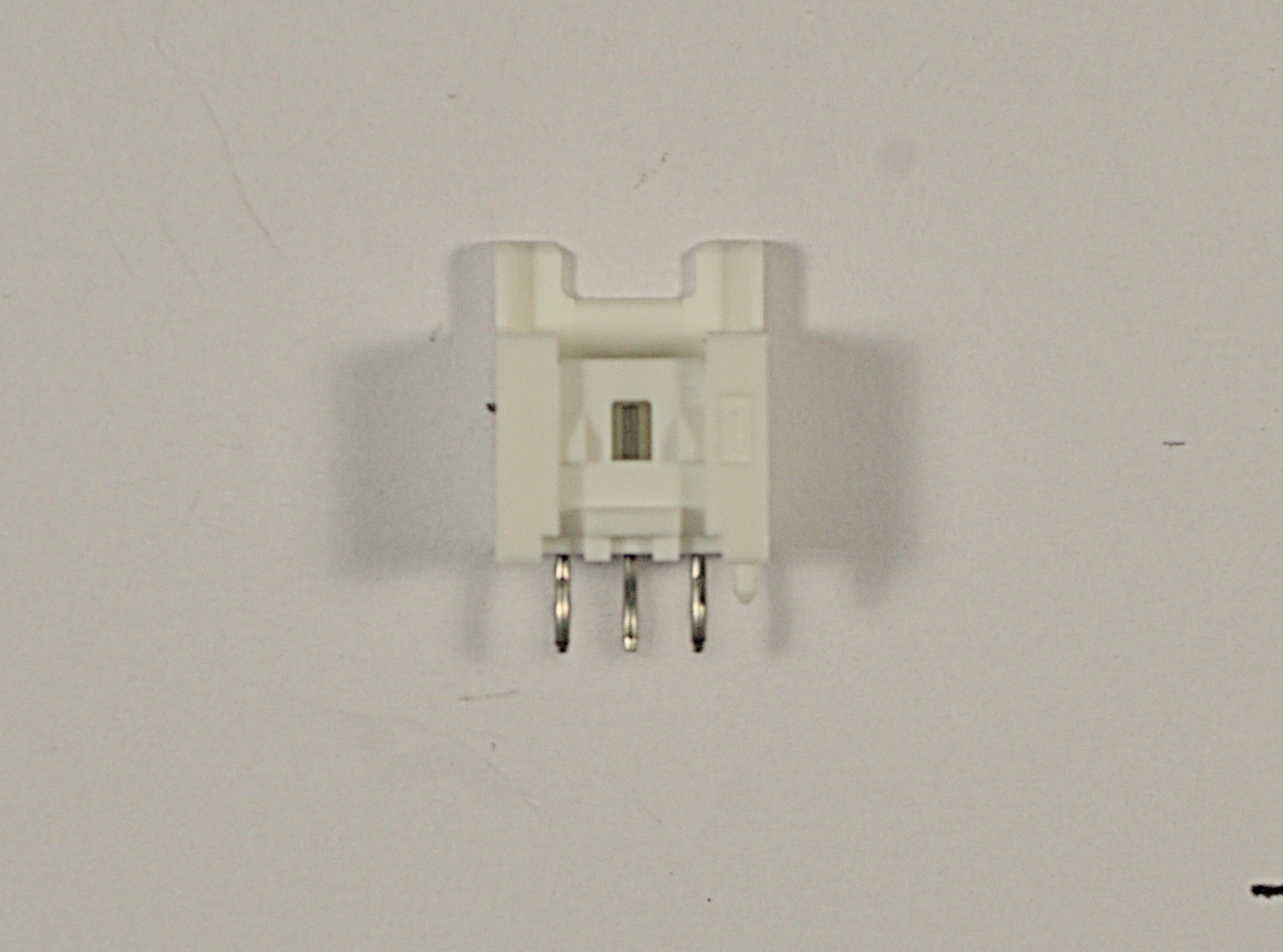
Solder analog and I2C plugs.
[!note] Removing Alignment Pin The plugs may come with an alignment pin on the bottom of the plug as can be seen in the picture below. Since the PCB has no alignment hole, this pin must be removed using a pair of flush cutters before soldering.
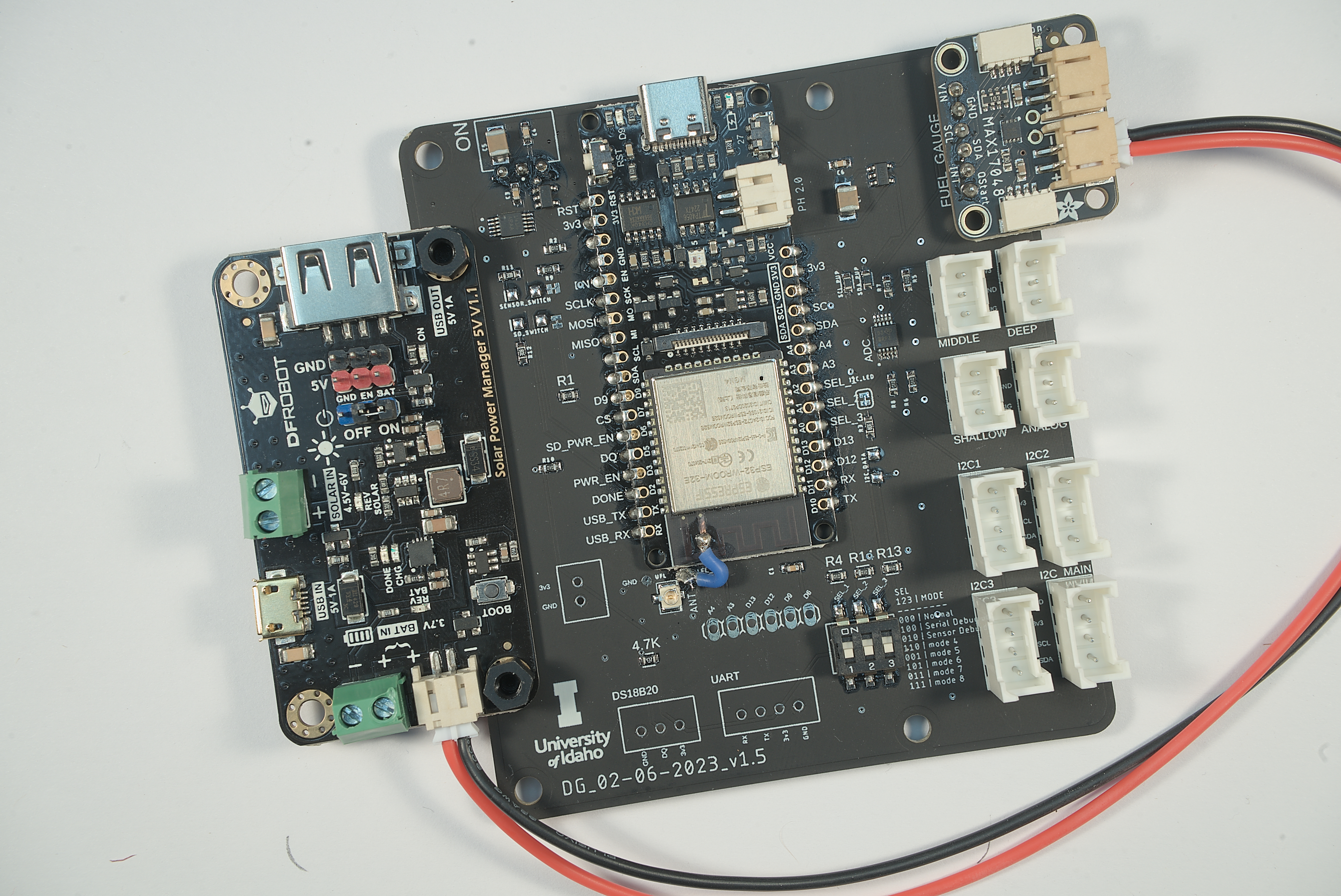
- Attach Solar Manager with M3 bolts.
- Make battery/charging cable using instructions from [[crimping guide]].
- Optional: perform antenna mod following directions in the antenna modification guide